🚘 Motor Wiring Diagram Single Phase With Capacitor ⭐
5 Easy Facts About read car electrically wire Described
Motor Wiring Diagram Single Phase With Capacitor
. ) My auto is often a 1989 Chrysler lebaron turbo. Is it possible to make sure you send me a wiring diagram for that ignition coil on the SMEC(motor Pc)? Can Additionally you send me the wiring diagram of the decide on-up coil on theThese chargers along with the on-board charger can be employed by the customer to cost his EV from his house electrical power outlet once he/she gets it home. But these chargers are extremely essential and do not include any Superior capabilities and for this reason would Ordinarily take all-around eight hrs to cost an average EV.
Motor Wiring Diagram Single Phase With Capacitor
Depending upon the handbook editor, this image could show a two cells battery or happen to be employed simply to generate the whole diagram just a little simpler to read.Determine 1 is a simple wiring diagram displaying a fog lights circuit. The circuit contains a battery, 20A fuse (utilized to safeguard the circuit), a change (Situated over a sprint panel), and two fog lights. Ground returns are proven by the ground symbol of a vertical line with 3 horizontal lines. Not all wiring diagrams display ground wires, and it truly is assumed the bottom symbols show wires that happen to be linked to the unfavorable battery terminal. This diagram is strange in that the presence of 12V is illustrated Using the circuit in each "ON" and "OFF" states. Red strains indicate the existence of 12V and black strains stand for the bottom side of your circuit that connects for the battery\’s destructive terminal. In the circuit "OFF" Component of the diagram, 12V is revealed to get present through the battery, with the fuse and also to the open sprint change.
Motor Wiring Diagram Single Phase With Capacitor
) Have got a code PO106 even All things considered codes deleted without the need of even starting engine all over again Will need wiring pin to pin on MAP sensor to ECMOther remedies contain showing just one procedure\’s wiring circuit on a web page, by way of example, just displaying the wiring diagram to the headlights. This functions pretty much and was carried about into the digital age.
Motor Wiring Diagram Single Phase With Capacitor
. Managing high amps by way of a compact change would cause the switch to burn off out and fall short, potentially starting a hearth.3 hours back WebAs stated just before, the wiring diagram shows both equally the RF flip sign and Passenger Outside the house mirror are on the exact same circuit, in fact the mirror is spliced to the same wire in the BCM ahead of under-going …
Motor Wiring Diagram Single Phase With Capacitor
John Harvards presents an automobile electrical process ebooks obtaining manual, and the knowledge is totally goal and authentic. We employ both equally AI and big info in proofreading the gathered information and facts.This know-how we use to assemble our listing depends on several different variables, together with although not limited to the following:
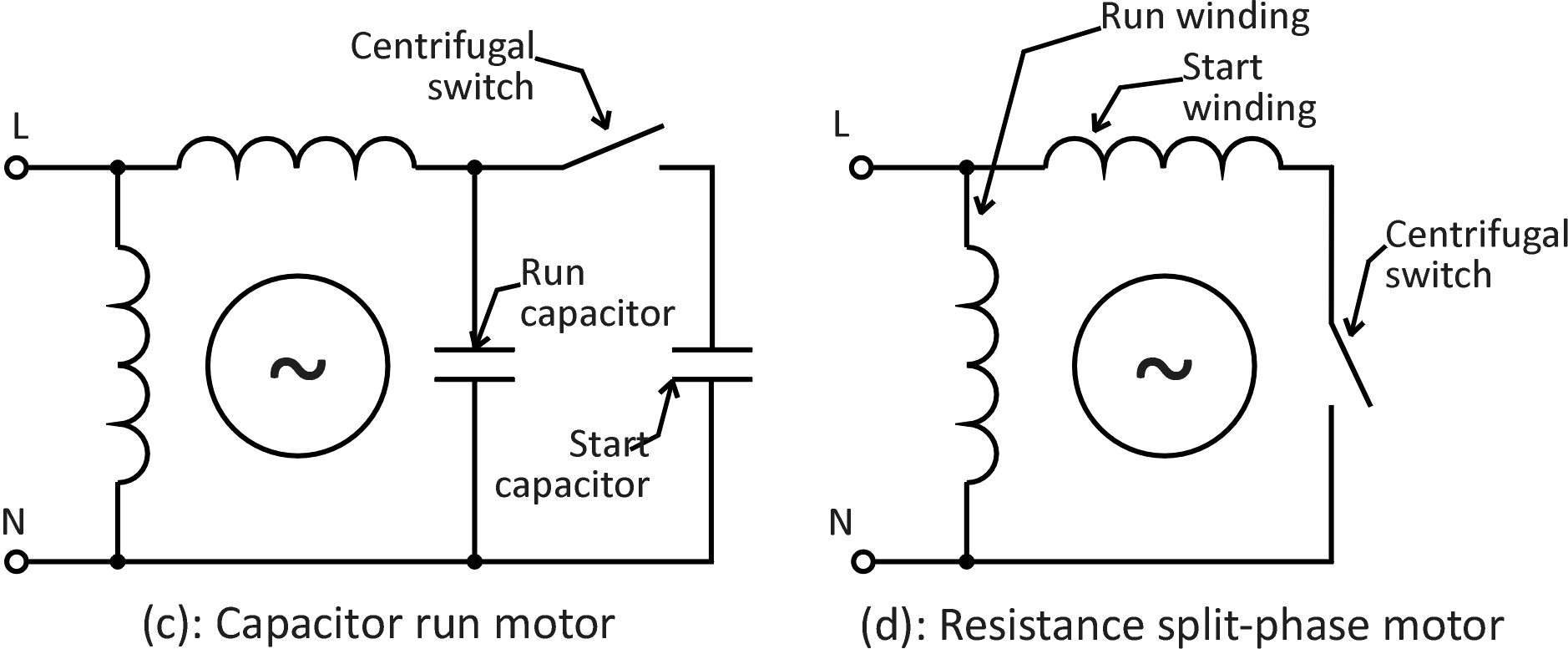
When The Motor Is Started, Once The Motor Speed Reaches About 80% Of The Rated Speed,.
Capacitor single phase motor wiring diagram. Capacitor start capacitor run induction motors are single phase induction motors that have a capacitor in the start winding and in the run winding as shown in figure 12 and 13. Types of single phase induction motors electrical a2z single phase induction motors are traditionally used in.
Single Phase Motor With Capacitor Forward And Reverse Wiring Diagram.
85k views 1 year ago single phase motor wiring diagram with capacitor start and capacitor run in this video we will learn how to connection of single phase motor with two. Types of single phase induction motors single phase induction motor from electricala2z.com motor wiring diagram single phase with capacitor. 6 lead single phase motor wiring diagram with capacitor from lh6.googleusercontent.com.
Single Phase Capacitor Start Capacitor Run Motor Wiring Diagram The Above Diagram Is A.
Single phase motor wiring diagram with capacitor start. Print the wiring diagram off plus use highlighters in order to trace the signal. Arts and crafts ideas for christmas options maintain it uncomplicated and slice up some development.
Single Phase Induction Motors Electric Motor Diagrams Types Of Ac Capacitor Wiring Diagram And A Part 2 What Is Psc Aspina An Overview Circuit 2Hp How To Use Vfd For Should.
This motor has two identical main winding’s arranged for either. Single phase motor with capacitor forward and reverse wiring diagram source: Electrical electrical wiring is a potentially hazardous task if carried out improperly.
Single Phase Motor Wiring Diagram And Examples Wira Electrical Terminal Identification Does Every Single Phase Ac Motor Require A Capacitor To Run Quora Weg.
Capacitor wiring motor phase single diagram run start. Single phase capacitor start capacitor run motor wiring diagram ac80, ac90, ac100 single phase motors;. Wiring diagram for a single.
Motor Wiring Diagram Single Phase With Capacitor
This publication is usually suggested for it isn't going to interrupt you with these difficult level to understand. It will certainly cause you to pleasurable Along with the lesson to acquire each time you've it. Very simple and likewise uncomplicated to check out and in addition understand make A lot of people are fond of this sort of guide.A steady and dependable offer of electric power during your auto is important In regards to your convenience and also your security. Our in depth choice of good quality electrical cabling will come in a variety of amp capacities, colors and lengths.
Motor Wiring Diagram Single Phase With Capacitor
You can find an inherent challenge with the look on the fog lights circuit as demonstrated in Figure one. These specific fog lights involve higher amperage (8A each, or 16A whole) within the battery to work and this substantial electrical load needs to travel by means of the many wires and sprint panel swap to get to the lights. The wires, and particularly the swap, would have to be major-obligation to manage the high present. An easy Option is definitely the addition of a 12V relay as proven in Determine 2.The still left cooling lover receives electrical power within the 40A fuse to the Purple wire at cooling supporter relay #one (terminal B3). The PCM reduced pace cooling fan relay Handle (42) is grounded from the PCM delivering a ground at terminal B1 (DK GRN) wire at cooling enthusiast relay #one. On a similar relay, terminal C3 gets electricity within the 10A fuse over the ORN wire.


